Frame rotation and wind direction
The ProMeteo library processes time series of the wind vector components u, v, and w, which are originally defined in the intrinsic Cartesian coordinate system of the sonic anemometer. These reference frames vary depending on the specific instrument model. A list of supported models is provided in the welcome page.
ProMeteo provides tools to:
rotate the reference frame to alternative coordinate systems:
LEC (Local Earth Coordinate);
Streamline, following the procedure described in [Kaimal1994];
compute the horizontal wind direction following meteorological conventions.
Rotation to LEC reference
The LEC (Local Earth Coordinate) system is the meteorological standard. In this system:
u is the zonal wind component. It is aligned with the x-axis, pointing from West to East, and is positive when the wind blows from the West (i.e., towards the East);
v is the meridional wind component. It is aligned with the y-axis, pointing from South to North, and is positive when the wind blows from the South;
w is the vertical wind component. It is aligned with the z-axis, pointing upwards, and is positive when the wind blows upwards.
This transformation is handled by the function:
pre_processing.rotation_to_LEC_reference()
To perform this operation, the sonic anemometer model and the azimuth angle (i.e., the orientation of the sensor head with respect to the geographic North) must be known.
RM Young 81000
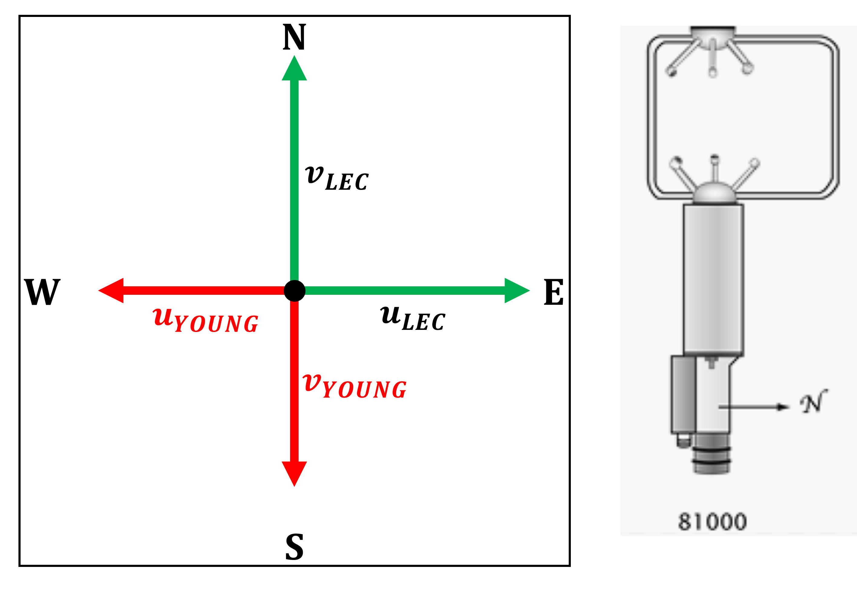
The u and v components measured by the RM Young 81000 are inverted with respect to the meteorological convention. The w component correctly represents the vertical velocity.
Transformation formulas:
In matrix notation:
Campbell CSAT3
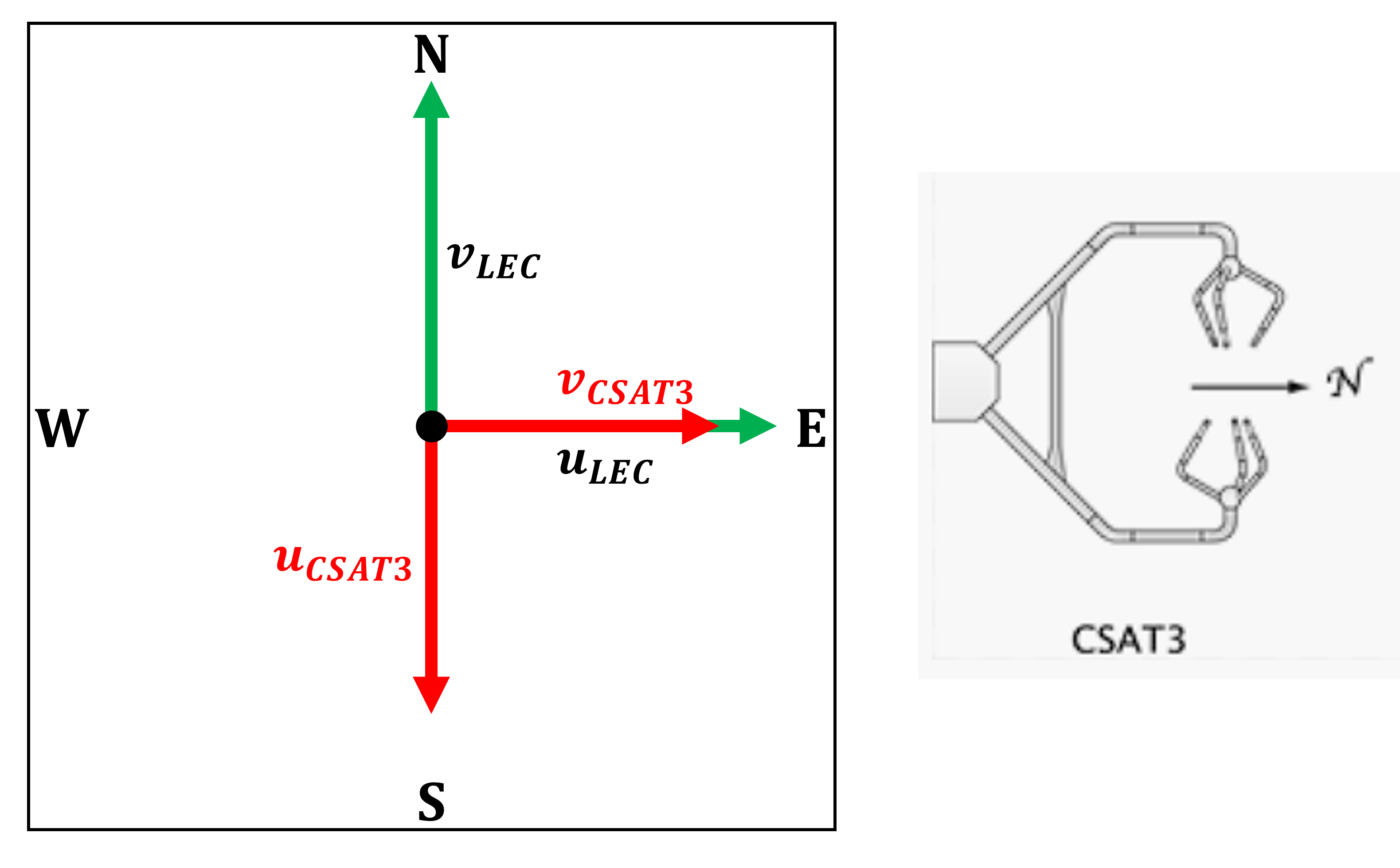
For the CSAT3:
the u component in LEC corresponds to the instrument’s v component;
the v component in LEC corresponds to the negative of the instrument’s u component;
the w component is already aligned with the vertical.
Transformation formulas:
In matrix notation:
Azimuthal correction
If the instrument is not oriented with its head pointing North but instead at a certain angle, known as the azimuth, relative to North, the transformation previously defined leads to a reference frame similar to the LEC system, with the y-axis aligned with the direction specified by the azimuth.
Therefore, an additional rotation is required,
defined by the azimuth angle \(\alpha\), which is provided as input to the function
and specified in the config.txt file through the azimuth parameter.
The corresponding rotation matrix is:
This matrix is then applied to the wind vector to align it with the true North-oriented LEC system.
Streamline rotation
An alternative reference frame is the physical streamline (PS) coordinate system, which is defined directly by the structure of the flow itself. In this system, the orthonormal basis vectors \((e_1, e_2, e_3)\) are oriented such that:
\(e_1\) is tangent to the local mean streamline;
\(e_2\) is aligned with the principal normal to the streamline;
\(e_3\) is aligned with the binormal direction.
This approach follows the procedure described in [Kaimal1994] and is widely used in boundary-layer meteorology to simplify the analysis of turbulence and fluxes.
The rotation to the streamline frame is performed using the double rotation technique, which aims to orient the coordinate system such that the new velocity components satisfy the following conditions:
Here, \(\vec{U} = (u, v, w)\) are the instantaneous wind components in the original (sensor-based) frame, and \(\tilde{\vec{U}} = (\tilde{u}, \tilde{v}, \tilde{w})\) are the components in the streamline frame.
The procedure involves:
Computing the mean wind vector \((\overline{u}, \overline{v}, \overline{w})\) by applying a centered moving average to each component. The averaging is performed using a sliding window, whose length is provided by the user through the configuration parameter
window_length_averagingin the fileconfig.txt.calculating the angles \(\theta\) and \(\phi\) that define the orientation of the mean wind vector in the original frame. These angles are computed using the following equations:
\[\theta = \arctan\left(\frac{\overline{v}}{\overline{u}}\right), \qquad \phi = \arctan\left(\frac{\overline{w}}{s}\right), \qquad s = \sqrt{\overline{u}^2 + \overline{v}^2};\]where \(s\) is the magnitude of the horizontal wind vector.
applying the following rotation matrix:
This operation effectively removes the mean crosswind and vertical components from the signal, aligning the flow with the x-axis in the new reference frame.
In this system:
\(\tilde{u}\) is the streamwise velocity component, aligned with the mean horizontal wind;
\(\tilde{v}\) is the crosswise velocity component;
\(\tilde{w}\) is the normal-to-the-streamline velocity component.
This transformation is applied using the function:
pre_processing.rotation_to_streamline_reference()
It is important to note that this rotation is data-driven and does not require information about the sensor model or azimuth.
Horizontal wind direction
In meteorology, the horizontal wind direction is expressed as the direction from which the wind is blowing, measured clockwise from the North. For example, a wind direction of 90° indicates wind blowing from the East.
In ProMeteo, the wind direction is computed starting from the averaged horizontal components of the wind vector, rather than averaging wind direction angles themselves. This distinction is crucial: wind direction is a circular quantity in the range [0°, 360°), and taking the arithmetic mean of such angles can lead to incorrect results. For instance, averaging 350° and 10° should yield 0°, but a naïve mean would result in 180°, a completely incorrect value. To avoid this, ProMeteo first averages the horizontal components of the wind vector and only then computes the wind direction.
The averaging operation is performed using the function core.running_stats(), which applies a centered moving average over a time window
whose duration is defined by the parameter window_length_averaging in the file config.txt.
This operation is performed upstream of the wind direction calculation, ensuring robustness and physical consistency.
The main script (main.py) chooses the method of wind direction computation,
depending on which reference frame has been selected in the configuration file.
Wind direction in the LEC system
If the LEC reference frame is selected, the main script first applies a rotation of the wind vector to the LEC system
by calling pre_processing.rotation_to_LEC_reference(). This function requires the model of the sonic anemometer
and the azimuth orientation (The angle between the direction the instrument is facing and true North, measured positively in the clockwise direction).
Once the wind components have been rotated to the LEC system, the horizontal components are averaged using core.running_stats().
Then, the wind direction is computed from the averaged components using the meteorological convention via:
This calculation is implemented in the function frame.wind_dir_LEC_reference(), which at this stage does not require
any additional information about the instrument model or azimuth, as these were used upstream in the coordinate rotation.
Wind direction in the streamline system
If the streamline coordinate system is chosen, the main script performs the streamline rotation using
frame.streamline_rotation(). This procedure, as described above,
does not require knowledge of the instrument model or orientation.
However, for consistency with the meteorological definition of wind direction (referenced to North), the direction is computed in the LEC frame. The steps are as follows:
Apply the streamline rotation to the original time series;
use
core.running_stats()to compute the averaged horizontal components in the original (sonic) coordinate system;pass the averaged components to
frame.wind_dir_modeldependent_reference(), which performs a model-dependent rotation to a LEC-like reference frame, where the y-axis is oriented at an azimuth angle with respect to North, using the instrument model and azimuth.
The wind direction is then computed as:
where \(\alpha\) is the azimuth angle.
Thresholding on wind speed
In both cases, it is possible, and recommended, to set a minimum threshold on the horizontal wind speed.
This threshold is an input of the mentioned functions and can be defined in the configuration file through the parameter wind_speed_threshold.
When the magnitude of the horizontal wind vector is below this threshold, the direction is set to NaN,
as it is considered not meaningful. This ensures that very low-speed or stagnant wind conditions,
which may introduce noise or spurious directional values, are properly filtered.